 |
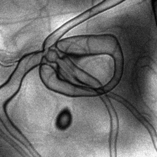
Caustic and Astigmatism Image size : 10 Ám This picture displays the so-called caustic representative of huge astigmatism aberration. The image was taken at the apex of a MFM tip producing a huge magnetic field. This important electro-magnetic field acts on the beam as an aberrated lens, which refracts and focalizes a part of the beam. (Caustic word originates from the Latin causticus : burning) |
|---|
| Domain walls and spaghetti Image size : 1 Ám The "spaghetti" displayed here are magnetic domain walls in an iron-palladium alloy. The color is representative of the magnetization direction while the intensity of the color shows the intensity of the magnetic induction. This alloy observed in plan view reveals its Up and Down magnetic domain structure by means of the Bloch walls separating them. |
 |
|---|
 |
Vortex and defocalisation Image size : 200 nm A magnetic vortex found in an iron dot is represented by means of Fresnel contrasts. The defocalisation enables to observe interferences between electrons travelling around the vortex core. The magnetic vortex acts as a lens which concentrates the electron wave at the core location. The high coherence of this wave results in a complex fringe pattern instead of a simple white spot. |
|---|
| Thickness and bubbles The TEM sample of iron-platinium alloy exhibits a lot of thickness variations along the area of imaging. The black contrasts observed here correspond to equal thickness areas and are forming a nice structure which could be associated to a fluid distribution. |
 |
|---|
 |
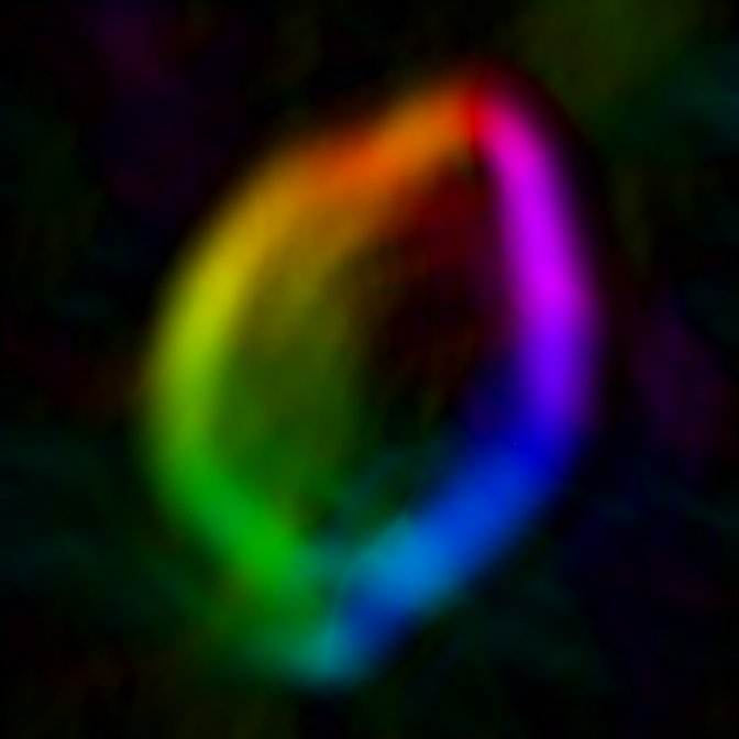
Lemon and rainbow Image size : 500 nm This lemon shape was obtained performing a phase retrieval on a simple hole in a carbon membrane. Retrieving a pseudo-magnetic distribution from the phase result in a strange form defined by the boundaries of the hole. |
|---|
| Iron and Palladium Image size : 100 nm Fresnel contrasts obtained on a transversal view of iron-palladium alloy. The intense bright spots correspond to the Bloch domain walls separing Up and Down domains. The fringes observed correspond to wave diffraction at the sample edge and interfaces. |
 |
|---|
 |
Phase and cosine Image size : 150 nm Quite same field of view as in the previous picture. This time is the phase that is displayed. The magnetic phase shift was obtained by electron holography and is displayed here by its cosine. Thus black and white lines correspond to iso-phase lines which represent the magnetic flux information. |
|---|
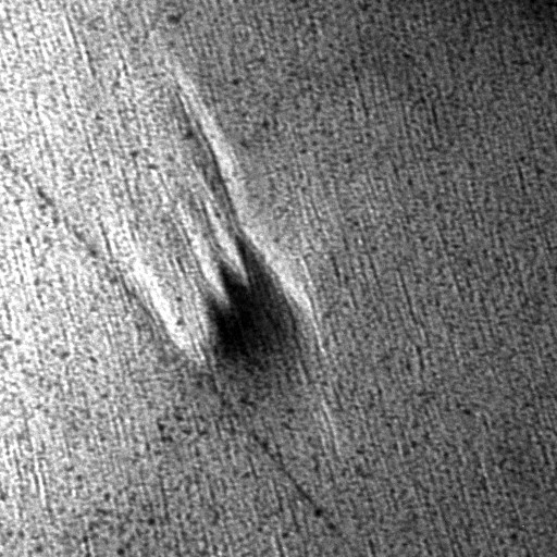
| Bear and Platine Image size : 1 Ám This bear foot print is a structural defect in a iron-platinium prepared by ion polishing. Its origin is unknown. |
 |
|---|
 |
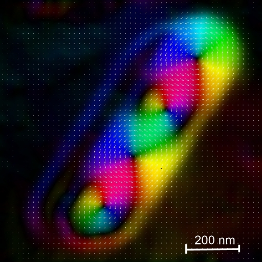
Cobalt and vortices Image size : 200 nm This is a magnetic mapping of a cobalt cristalline dot. The magnetic structure is decomposed in two vortex states with opposite chiralities. The vortices are easily seen at the dark spot locations, where the magnetization is mainly out of plane. This magnetic structure depends on the magnetic history of the sample. |
|---|
| Dots and ... Image size : 1 Ám One more magnetic map but on iron dot. The structure is defined by a majoritary (yellow) domain and a small (blue) antiparrallel domain. This dissymetry was obtained by apllying a magnetic field of around 1 Tesla on the sample. The black line separing the two previoulsy described domains is a finite Bloch wall. On the lower end of the dot one can observe another domain wall tending to adopt a vortex configuration. |
 |
|---|
 |
Without a title Image size : 500 nm An old image without any description but displaying a strange perfect circle. |
|---|
| Magnetic flux lines Image size : 400 nm Another way of displaying the magnetic information in electron holography. Obtained on iron-palladium alloy in transverse view. The flux lines show that the magnetic flux is not confined in the material (around the domain walls, represented by the vortex along the layer) but are radiating outside the sample with stray fields. This radiation is traditionally used to read data in magnetic memories. |
 |
|---|
 |
How many lines Image size : 500 nm Typical hologram in vacuum. The contrast (here about 70 %) and the fringe spacing (here around 10 nm) are directly related to the information quantity that will be reachable in the reconstructed phase. |
|---|
| Smooth trench Image size : 20 Ám This image was obtained in a Scanning Electron Microscope shipped with a ion beam column. The MgO substrate has been drilled to enable the observation of the magnetic layer (under the trench) by Transmission microscopy. The final thickness of the sample should be less than 200 nm to let the electrons traveling through. |
 |
|---|
 |
Colour and lines Image size : 3 Ám This is a simulation of the stray field radiating aoutside a MFM tip (in blue and orange). The magnetic induction is given alternately by 2 colors (orange and blue for direction of the field inside the tip and green and pink for the perpendicular direction). |
|---|
| Seahorse Image size : 1 Ám This image was taken on iron-platinium alloy. The origin of the fine structure of that "seahorse" is uknown. |
 |
|---|
 |
Gold and fields Image size : 300 nm Magnetic stray field produced in the vacuum by an iron-palladium layer. The layer is dispalyed in gold and the vacuum is in green colour. Red and blue colors correspond to the left or right orientation of the magnetic induction just on the top of the layer. |
|---|
| Interfering interferences Image size : 1.5 Ám Interferences created by both an electrostatic biprism (from NW to SE in the image) and a carbone nanotube (from NE in the image). These interference patterns are recovering and creating a chessboard display at the the center of the image. |
 |
|---|
 |
Diamond and Landau Image size : 1.5 Ám Magnetic maping af a 4-Landau state iron dot. Four vortex can be seen inside the dot (the four dark spots). Each of them defines an inversion in chirality reagrding its neighbours. |
|---|
| Dots and oxydation Image size : 500 nm Oxydation on the extremity of an iron dot. The strange "living" shape is due to the cracking of the oxydized barreer due to the high electron energy. The dot is above the picture. |
 |
|---|

updated : 01/2011